Boeing 747-400 Standard Procedure's
Guide
An illustrated guide to getting started
with the PMDG 747
Contents
Getting Started
This document is © 2005 - Jared "Smitty" Smith. You are
free to translate this article as long as a link is provided to this
document. If you contact
me, I will provide a link to your translation.
Translations:
DUE TO THE MASSIVE AMOUNTS OF E-MAIL I RECEIVE REGARDING THE PMDG 747, I WILL NO LONGER BE RESPONDING TO YOUR E-MAILS ASKING FOR HELP OR CUSTOMER SUPPORT. IF YOU ARE HAVING PROBLEMS, POST THEM ON THE PMDG SUPPORT FORUMS. I HAVE NO CURRENT PLANS FOR UPDATING THIS GUIDE (EXCEPT IF ERRORS ARE FOUND) OR FOR WRITING AN FMC GUIDE. THANKS!
You can also redistribute
this as long as you link to the original (which
will always be kept up-to-date) found at http://smithplanet.com/fs2004/pmdg/index.htm
A PDF version is available by clicking the icon below.

This guide will:
- guide you through the standard startup, taxi, takeoff,
climb, cruise, approach, and landing procedures for the PMDG
747.
- provide an illustrated guide to the major systems and controls of the 747.
- provide an simple, logical, and easy to understand method for operating
the 747 similarly to real-world operations.
This guide will NOT:
- be a substitute for the official PMDG manual.
- teach you all operations of the aircraft.
- teach you how to program and use
the FMC beyond what is needed to minimally operate the aircraft.
- teach you about or how to fully use the autopilot functions.
You will notice that this guide deviates from the published Normal Procedures
checklist. This is done to facilitate learning the 747 systems, to save time,
and to only focus on the systems that are likely to be necessary to establish
an operational aircraft. I believe all of the procedures and information
here to be factual, though it is often overly simplified and not necessarily
in the correct order. If there is something that is incorrect or unclear,
please let
me know. IF YOU HAVE QUESTIONS REGARDING THE OPERATION OF THE AIRCRAFT,
REFER TO THE MANUAL OR POST THEM TO THE PMDG SUPPORT FORUM. I WILL NOT ANSWER
STUPID QUESTIONS THAT ARE ANSWERED ELSEWHERE. :-) On the other hand, if you
have a legitimate question or concern, please contact me and I'll be happy
to respond.
Requirements:
- The PMDG 747.
- Your aircraft positioned at a gate a KLAX (this tutorial uses gate I1).
- 1/3 or less fuel in the fuel tanks. This can be set in the PMDG... General...
Options... Fuel settings.
- A cold and dark cockpit.
I STRONGLY recommend downloading
this cold/dark scenario and flight plan as all graphics and
panel states will match those found in this guide. The flight plan
followed in the tutorial (KLAX-KEDW) is also provided. After downloading,
extract the ColdDarkKLAX.FLT file
to your Flight
Simulator 9\Flights\PMDG folder. Extract the ColdDarkKLAX.sav file
to the Flight
Simulator 9\PMDG\747400\PanelState folder. Extract KLAXKEDW.rte
to your Flight Simulator 9\PMDG\FLIGHTPLANS folder. When
you are done, open
FS9 and click Select a Flight (or
Flight... Select a Flight if you're already in the cockpit). Select
PMDG under Choose a Category and then select
ColdDarkKLAX under Choose a flight. Click
OK to enter the dark cabin of your 747 which is parked at gate
I1 at KLAX.
There is a bug with the default cold/dark scenario file shipped
with the PMDG 747. Do not use it. Either download the files above,
create your own, or read
here to learn how to fix the supplied file.
Preflight
You just stepped through the cockpit door of the cold and dark 747-400, the
most magnificent passenger aircraft on the planet. You are the captain on
this short flight from KLAX to KEDW and will direct all flight operations.
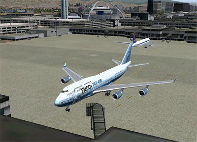
You'll notice that the cockpit is totally powered down. Usually while parked
at the gate, there would be some power already flowing and if the pilot that
flew the plane before you is nice, he'd have left a light on for you.
But your plane's been parked for awhile and is totally powered down.
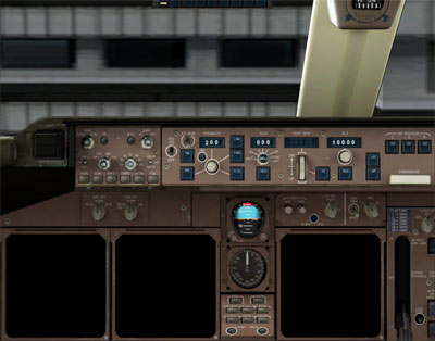
We first want to get some power flowing to the basic cockpit systems. Open
the OVHD panel. The OVHD button is found on
the panel switcher. If the panel switcher is not visible, click on the center
console pillar below the compass to display it.

The overhead panel is roughly divided into the following sections.

Turn ON the BATTERY.

Left click to press the button to turn on the battery. The battery button
has a protective cover over it that closes when the battery is turned on.
If it is closed, you can right click to open it, then left click on the button
to turn the battery off. Let's leave the cover closed so we
don't accidentally turn it off. The battery should remain on at all
times as it provides a backup power source to critical flight instruments.
The battery alone does not provide all the power you need to operate the aircraft.
It will give us basic power for over 30 minutes.
Turn the STANDBY POWER switch to AUTO.

The switch is rotated to the right by right clicking on it. All switches are
rotated to the left by left clicking.
The standby power switch tells the electronics system of the aircraft where it should
draw it's electrical power from. When set to OFF, only a few systems will
be powered by the battery. AUTO allows the electrical system to draw the
power from the best available power source. BAT will only draw power from
onboard batteries, giving you about 30 minutes of power. We'll leave this
switch on AUTO and the electrical system will handle the distribution of
power automatically.
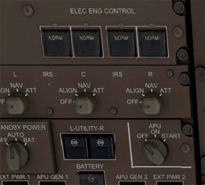
Set all four ELEC ENG CONTROL switches
to NORM.
Set
the BUS TIE switches to AUTO.
Set
the GEN CONT (generator control)
switches ON.
Ensure that the Hydraulic DEMAND pump switches are set
to OFF.
Turn the ENGINE hydraulic pump selectors ON.

The ELEC ENG CONTROL switches allow the electrical system to operate the
engines. These buttons also have guard covers, so right click if you need
to open them and be sure to close the guard when you're done. The 747's engines
are primarily controlled by electronic systems rather than hydraulic or pneumatic
systems. If the electrical engine control system for an engine fails, you
can click the button again to switch to an ALTN (alternate) electrical system.
The BUS TIEs allow power to flow properly throughout all
systems on the aircraft. The 747 has multiple electrical systems and
many fall back systems in case something goes wrong.
Turning the GENerator CONTrol buttons ON will allow the engines generators
to provide electrical power to the system. Don't worry if OFF is illuminated
on the GEN CONT buttons - this just indicates that the system is currently
off (engines are off), but that the generator control system will be ON as
soon as the engines are started.
Typically, the hydraulic system on the aircraft is pressurized by the engines.
If an engine fails, the hydraulic system can be powered by bleed air or by the
electrical system. Because the engines and bleed air are not currently available,
setting the Hydraulic DEMAND pump switches to OFF ensures that electrical power
is not currently used to pressurize the hydraulic system.
Turn on EXT PWR 1 and, if available, EXT PWR 2.

External power is available from a cable connected to your airplane from the
airport electrical system. AVAIL will be displayed if external power is available.
Ground power is only available if your parking brake is set (CTRL + .) and
you are stopped at an airport. External Power 2 may not be available at all
airports. If it is available, turn it on. If not, don't worry about it - one
source of external power will suffice.
In the 747, if a switch has two horizontal or vertical lines displayed on
it, then it is on. The EXT PWR indicators also display the word ON if power
is flowing.
The flight attendants are now entering the aircraft, so turn ON UTILITY
L and R. This will supply electrical power to the passenger compartment
lighting, galleys, doors, etc. It also allows the baggage compartment
doors to be operated.
Any time the aircraft has power supplied to it, the NAV lights
should be on. This alerts the ground crew that the aircraft is powered and
under pilot control. Turn on the NAV lights. You can also turn on
the LOGO and WING lights at this time.

The external light controls are found in the lower right of the OVHD panel.
We will not turn on the BEACON lights until we're ready to be pushed back
or begin taxiing. The STROBE lights aren't turned on until we're ready to
takeoff.
You can now set cockpit lighting as desired. This is done
with the three lighting switches (CKT BKR OVHD PANEL, GLARESHIELD PANEL/FLOOD,
and DOME) found in the lower left of the OVHD panel. Right click to turn up the lights. Left click to dim them.

If it is daylight outside, then these will make little difference. The STORM
switch provides a quick mechanism for turning all of the cockpit lights on
to maximum brightness. It would be enabled if flying in poor weather to minimize
the blinding effects of lightning flashes. Storm lighting is not modeled in the PMDG
747.
ARM the emergency lights. This is done by right clicking on the cover to close
the guard. The emergency lights switch is located at the top of the OVHD
panel and may be hidden behind the panel switcher.

Ensure all control surfaces are properly positioned. Ensure
that the flaps are up (F5 key) and that the gear position handle is in the
DOWN position. This is also the time to perform your external walk around
to inspect all flight control surfaces.
We will now begin aligning the Inertial Reference System. The Inertial Reference
System is comprised of three gyros. These gyros detect very faint movements
of the aircraft in all directions. They send information to the flight computer
indicating if the aircraft is moving, which direction it is moving, and how
fast. The IRS is the primary mechanism for providing accurate positioning
and automated flight control for your aircraft. In order to function properly,
the Inertial Reference System must be powered up and given an initial 'home'
position from which all movement will be referenced. The IRS can only be
powered and aligned while your aircraft is stationary on the ground.
Set each of the three IRS switches from OFF to NAV to ALIGN. This
is accomplished by right clicking then left clicking each of the IRS switches.
The gyros for each IRS will begin to spin and the system will begin powering
up.
Actual alignment time is 10 minutes, though this can be customized in the
options (PMDG... General... Options... IRS). As it'll take us a while to
finish powering up the aircraft, the 10 minute time period will be fine,
but you may want to shorten this time period because you'll be an expert
at firing up this bird after a few tries and may not want to wait around
for the IRS to finish aligning. Remember, you cannot properly align the IRS
system if you are moving.
Before the IRS can be properly aligned, it has to know where the aircraft is
currently located.
Open the FMC by clicking the FMC button on the panel switcher.
Click the FMC button located at LSK (Line Select Key) 1L (this
means the first button down on the left). Click IDENT at LSK 1L. Ensure
that the FMC is reporting accurate information about your current aircraft. Click
POS INIT at LSK 6R. The POS INIT page of the FMC allows you to determine
and input your aircraft's current position.
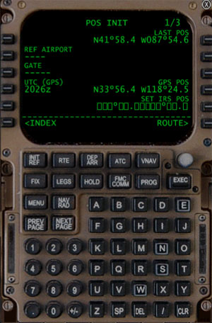
The top line displays LAST POS. This is the coordinates for the last position
the flight computer remembers being at. Click LSK 1L to update the flight
computer with your current position. This step only tells the flight computer
where your plane is, it does not align the IRS system.
Press and hold the CLR button in the lower right of the FMC
to clear any messages that may be currently displayed. To orient the IRS
system,
first click on LSK 4R (the
GPS POS line). This will copy your location coordinates as reported by
the onboard GPS system and store them in the scratchpad (the bottom
display-only line of the FMC display). Click
on LSK 5R (the
SET IRS POS line) to upload the coordinates to the IRS system.

Close the FMC by clicking the FMC button on the panel switcher
or by clicking the X button in the upper right of the FMC. On the overhead panel, turn
the IRS switches back to NAV by right clicking once on each of them. The IRS system is now properly aligned, though it may take up to 10 minutes
(depending on your settings) to complete the initialization process. The time remaining will display on the Navigation Display (ND). Your plane
now knows where it is at and can detect where it is going. This allows the autopilot
and flight computer to function properly.
Turn on all fuel XFEED (crossfeed) switches.
Fuel crossfeeds distribute fuel between fuel tanks. Enabling the XFEED
now ensures that if fuel is loaded into the aircraft on the ground that it can
flow freely throughout the system. As your plane may be fairly full
of fuel on departure, this also ensures that the XFEED switches remain on
once the engines are started. The switches display horizontal lines when
the XFEED is ON. The engine 2 and engine 3 XFEED switches have guards - right
click if you need to open them.
Ensure all fuel pumps are OFF. There should be no ON indicators
illuminated for any of the 16 fuel pumps.

Disable NACELLE and WING ANTI-ICE
Enable WINDOW HEAT

Nacelle anti-ice distributes air from the engines back onto the engine casing
to slow formation of ice. Wing anti-ice distributes engine bleed air to the
front of the wings. Both should only be enabled when the temperature is less
than 10° C and visible moisture is present - something that isn't likely for the Los Angeles area. Nacelle anti-ice should only
be enabled after the engines are started. Wing anti-ice should only be enabled
after takeoff.
Window heat will keep ice and condensation from forming on
flight deck windows. As the temperature and humidity change dramatically
during the stages of flight, WINDOW HEAT should be enabled at all times.
Wipers and washers should be used only during taxi and flight and only when
the windows are wet (in the PMDG, animated wipers are displayed in the virtual
cockpit only).
Turn YAW DAMPERS ON

Yaw dampers automatically provide rudder and flight control input to aid the
pilot and autopilot in maintaining smooth directional control. They help
keep turns smooth and the passenger vomit off the apholstery. They should
always be enabled during flight. The YAW DAMPER buttons are located at the
top right of the OVHD panel. INOP is also displayed as the yaw dampers
rely on hydraulic pressure to operate. Once the engines are started, they
will remain ON and INOP will disappear.
Rotate the APU switch to START (right click
twice). The switch will automatically set back to ON once the START command
has been given. It'll take several seconds for the APU to start.

The Auxiliary Power Unit is a fuel powered engine located in the tail section of the aircraft. It provides hydraulic and pneumatic pressure and electrical power to the aircraft. In short, it provides most everything the aircraft needs to function except for the main engines. Seeing as the passengers are beginning to board now, it's a good idea to now start the APU so the air conditioning and recirculation system can begin to work.
As soon as AVAIL displays on the APU GEN buttons, turn ON APU GEN 1 and APU GEN 2.
The aircraft is now being powered by the onboard APU. You will notice that
the aft fuel tank 2 PRESS indicator will extinguish. The APU draws its fuel
from the number 2 tank and when the APU is started, this fuel pump is automatically
turned on. The EXT PWR indicator(s) also extinguish and return to AVAIL if
external power is available. If external power is not available at your airport,
you can still perform all of the preflight operations with the APU started.
We'll now set up the air conditioning and comfort systems. These controls
are found at the right side of the OVHD panel.
First ensure that PASS TEMP and FLT DECK temperature
controls are set to AUTO. If you or the pax get too hot or cold,
you can adjust the temperature Colder or Warmer.
Make sure TRIM AIR
is ON. Trim air is hot air that is pulled from the engines. It is
mixed with the air in the airplane to control temperature.
Turn ON UPR and LWR RECIRC. This turns on fans that circulate
air throughout the fusilage.
If you're carrying sensitive cargo (vegetables, animals, etc.) in the
aft cargo hold, be sure to enable AFT CARGO HT before takeoff or it will
get VERY cold back there. You should not enable it until the cargo hold doors
have been closed.
Turn ON the GASPER. The gasper provides pressurized air to
the passenger seat comfort units in the overhead consoles - you know, the
adjustable control knob you can never adjust to blow just the right amount
of air in the right direction.
Turn all three PACK switches
to NORM.
Ensure the ISLN switches are open (horizontal lines displayed and VALVE extinguished).
Turn ON APU Bleed (located above the ENGINE BLEED label).
Turn ENGINE
BLEED ON for all four engines.
All systems should be configured as shown in this picture:

Air PACKS control the flow of air between the engines, the APU, the air conditioning
system, and all other pneumatic systems. Setting them to NORM allows the
pneumatic system to control the flow of air for all three air packs.
Opening the ISLN (isolation) switches allows the air to flow freely between the air packs.
Bleed air is air that is diverted from the engines and used to power the pneumatic system. We want to use bleed air from the APU at this time to pressurize the pneumatic system. This bleed air will soon be used to start the engines. By turning on the ENGINE BLEED switches now, bleed air will be available from each of the engines as soon as they are started.
Let's now continue to program the rest of our flight information into the FMC.
Open the FMC. The POS INIT page should still be displayed. Click the RTE button to move to the ROUTE page.
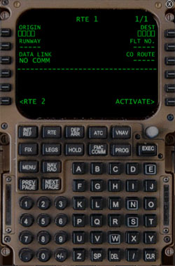
This is where you would typically program your full flight plan waypoints.
We will be using a previously configured flight plan for this flight. If
you are comfortable programming your own, you may, though the rest of this
tutorial uses specific waypoints and references from the supplied flight
plan.
Press and hold CLR to clear any messages that might be displayed in the scratchpad.
Enter KLAXKEDW into the scratchpad by pressing the letter
keys. Alternatively, you can enter text into the FMC by pressing the black
KBD bar to the right of the letter keys. KBD will be displayed. You can now
use your keyboard to type information into the scratchpad. Be sure to press
the black KBD bar again when you're done.
Press LSK3R (COROUTE) to load the flightplan into the FMC.
Departure and arrival airport, as well as all intermediate waypoints will
be loaded into the FMC. This loads a short flight from KLAX to KEDW (Edwards
Air Force Base).

Press LSK 6R (ACTIVATE) then press the EXEC button. This
will activate your flightplan and pass the relevant information to the flight
control computer.
Press LSK 6R (PERF INIT). This opens the performance initialization screen.

Any time you see boxes in the FMC, this indicates that information is required.
Enter 15000 into the scratchpad and press LSK 1R. This sets
our cruise altitude to 15,000 feet.
In the real 747, the pilot would have to calculate and enter the Gross Weight
into LSK 1L and ZFW (Zero Fuel Weight) into LSK 3R. In the PMDG, these can
be automatically estimated for you.
Press LSK 1L. This automatically enters the estimates for your weight parameters.
Enter 10 into the scratchpad and press LSK 4L. This sets
the required RESERVES for this flight to 10 percent. If your fuel goes below
this, you'll receive a low fuel warning.
Enter 100 into the scratchpad and press LSK 5L. This sets your COST INDEX.
Cost index uses a formula to determine how efficient you want your flight
to be in regards to fuel and time usage. This number is determined by the
carrier, but 100 is a nice number that will get us there relatively quickly.

Press LSK 6R (THRUST LIMIT) to display the thrust limitation settings used
for cruise and climbout. The default settings will work fine.
Press LSK 6R (TAKEOFF) to display the thrust setting used for takeoff.
Enter 20 into the scratchpad and then click LSK 1L to set
the Takeoff Flap setting. Flaps 20 is the standard flaps setting for takeoffs
in the 747. You can also use flaps 10, but it will take longer for you to
get airborne.
Press LSK 1R, 2R, and 3R to verify your V1, VR, and V2
speeds. These are speeds used to determine if and when you takeoff from
the runway.

Write down or remember your V2 speed as we will need this number in a moment.
Press LSK 4R to verify your takeoff trim settings.
Write down or remember the trim number as we'll need it also
in a moment.
Close the FMC.
Close the OVHD panel.
You should now see the main cockpit. By this time, the IRS should be properly
aligned and the ND (Navigation Display) should be displaying your current
heading, position, and flight plan legs. You can extend the range that is
shown on the ND by right or left clicking the range adjustment knob on the
MCP (Mode Control Panel).

Turn the F/D (Flight Director) ON. When the autopilot
is on, the Flight Director is what controls where your plane goes. When the
autopilot is off, the F/D will give us visual cues as to climb pitch and bank
angle to keep the aircraft flying safely.
Enter V2 speed into the IAS/MACH indicator on the
dashboard. You can adjust the autopilot indicator numbers by right
or left clicking around the edges of the appropriate knob. My FMC reported
a V2 speed of 144 knots, so I have entered 144 into the IAS/MACH indicator.
Immediately after takeoff, you will use aircraft pitch to maintain this speed.
Arm LNAV and VNAV by clicking on their respective buttons
on the MCP. LNAV will control the lateral movement of the aircraft (i.e.,
follow your flight plan direction) and VNAV will control the vertical movement
of the aircraft (get you to your cruise altitude and back down efficiently
and safely). At this time we are only arming these autopilot functions. They
will not actually control the aircraft until the autopilot is engages after
we are airborne.
Set HDG to 249. This is the runway heading for our takeoff
runway 25R.
Set ALT to 10000. You would typically set this to your initial cleared altitude as given by ATC. 10,000 feet will work nicely for this flight.
Ensure the autopilot DISENGAGE bar is UP.

Open the Throttle panel by clicking THR in the panel switcher.
Ensure that fuel control switches are set at CUTOFF (knobs pulled out and down). This will ensure that fuel will not flow to the engines.
Set trim to the number previously indicated in the FMC TAKEOFF
page. This is done with the 7 and 1 NUMPAD keys with the NumLock off. Adjust
the white area so that it coincides with the trim setting desired. My FMC
reported a trim setting of 5.5.

Close the Throttle panel.
Open the Communications panel by clicking COM
in the panel switcher. This displays the center console and radio stack.
Set AUTOBRAKES to RTO. This will initiate full braking if something goes wrong during your takeoff roll and you reject (decide to end) the takeoff. Rejected Take Off braking WILL stop the plane VERY quickly if things go badly before you takeoff.
Turn the TCAS switch from XPDR to STBY/TEST (left click once).
Wait a few seconds for the Traffic Collision Avoidance System test to complete.
Now move the TCAS
switch to TA/RA (right click four times). Traffic Advisory/Resolution
Advisory mode allows the flight system to alert you to any aircraft that
pose a potential collision risk and will instruct you in taking evasive maneuvers
if necessary.
Set the TCAS biasing mode switch to ABOVE. Because we will be taking off and climbing soon, this will filter traffic conflicts to those that are predominantly above your aircraft. You will set biasing mode to N (Normal) when you enter the cruise stage and to BELOW during your descent.
Ensure that NO SMOKING and SEATBELTS selectors are set to AUTO. AUTO will turn off the SEATBELT indicator when you are above 10,000 feet. If you'd rather control this manually, you can set it to ON and then turn it OFF when appropriate.
Lock the FLT DK DOOR. Due to FAA regulations, the cockpit door
must be locked and secured while the aircraft is in operation.

Close the COM panel.
Press the TFC button on the EFIS (Electronic Flight Information System)
Mode Control Panel. This will display any traffic that may
pose a collision threat to your aircraft on the ND map page.

Open the OVHD panel.
Open the EICAS by clicking on the EICAS button on the panel
switcher. Press the FUEL button in the EICAS MCP to display
the current fuel configuration of the aircraft. If you set fuel correctly,
you should have fuel in tanks 1, 2, 3, and 4. The center tanks and horizontal
stabilizer tanks should be empty.
Turn ON MAIN and OVRD fuel pumps for each tank that contains fuel. Note that even though PRESS does not display on AFT TANK 2 (because the APU system has overridden the fuel pump off status), you still need to press this button to explicitly turn ON this fuel pump.
Configure XFEED according to these guidelines:
- If tank 2 has more fuel that tank 1 AND tank 3 has more fuel than tank 4, turn all XFEEDs on.
- If tank 2 has less than or equal fuel that tank 1 AND tank 3 has less
than or equal fuel than tank 4, then XFEED 1 and 4 should be turned OFF
and the OVRD fuel pumps should be turned OFF.
In my configuration, all of the tanks had about the same amount of fuel, so
I have turned ON the fuel pumps for MAIN 1, 2, 3, and 4. The OVRD 2 and 3
pumps are left OFF. FUEL X FEED 1 and 4 are turned OFF (no horizontal line).
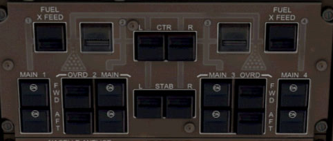
Close the EICAS and OVHD panels.
Pushback and Start
We're now fully configured to begin our pushback and engine start. The passengers
are on board and you've just been given your clearance. As things start to happen
very quickly from here on out, don't be afraid to pause your sim between steps.
Close all doors. You can open the DRS page on the EICAS to verify they are all closed.
Open the COM panel.
Right click on the RST button on the pushback guage to initialize the pushback system.
Use right and left mouse clicks to adjust DIST and DEG.
DISTance is the number of meters(?) to be pushed backward. After the pushback,
the ground crews can also turn your aircraft up to 90 DEGrees either direction.
L or R (Left or Right) indicates the direction your nose will be turned.
With our aircraft at Gate I1 at KLAX, a DIST of 30 and a DEG or L90 should
put us right in the middle of the taxi area and pointed toward the main taxiway.

As soon DIST and DEG are entered, left click on the RST
button to alert the ground crew that you're ready for pushback. Follow
the radio instructions from the ground crew and be sure to release and set the
parking brake (CTRL + . or switch on the throttle console) when instructed.
In the OVHD panel, turn ON the BEACON lights. This indicates to the ground crew that you will be starting the engines and moving the aircraft.
Set Hydraulic DEMAND Pump selector 4 to AUX. This
will power the #4 hydraulic pump with electrical pressure during engine start.
Set Hydraulic DEMAND Pump selectors 1-3 to AUTO.

Turn OFF all but one PACK selector. By doing
so, the majority of the air from the APU (and from other engines as they
are started) will be used to start the engines, rather than being distributed
for other things (passenger comfort, air conditioning, etc.).

Turn OFF autostart. We will be starting the engines manually because it's just cooler that way.
Turn ON continuous ignition. This will send a continual spark to the engines which will ignite the fuel when it is introduced.
Ensure all throttles are at idle (F1 key) because the FAA
and our passengers don't want us to spin circles when we start our outboard
engine.

Open the EICAS panel and press the ENG button on the EICAS MCP. You
want to keep the EICAS ENG display open throughout the starting process so
that we can monitor the engine performance and introduce the fuel at the
correct time.
In order to properly start the engines, you must complete the following tasks within about 15 seconds, so it may be helpful to read this section entirely before continuing.
Pull the Engine Start Selector for Engine 4.
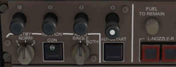
Quickly open the throttle panel. Watch the N2% RPM increase
in the EICAS display. Bleed air from the APU is being 'blown' across the engine
and is beginning to turn the turbines.
When the N2% RPM indicator on the EICAS reaches the magenta line (around
14%), switch the Fuel Control Switch for Engine 4 to RUN. The engine
should start up and then idle back. Don't you just love that sound!


Repeat this process for engine 1. Pull the Start Selector, wait for N2 to reach the magenta line, set Fuel Control to RUN.
Now do the same thing for engines 2 and 3. As soon as you get the hang of it, you can start engines 1 & 4 and engines 2 & 3 simultaneously.
If you later want to use the autostart functionality, make sure that
the Autostart switch is on and set the Fuel Control Switches for all
engines to RUN first, then simply pull the Start Selector for the engines
you want to start. The plane will start the engines automatically. As before,
engines 1 & 4
and engines 2 & 3
can be autostarted simultaneously.
Turn OFF the APU. The main engines are now powering
the electrical, pneumatic, and hydraulic systems. The APU is no longer needed.

Turn OFF APU Bleed Air.
Turn all PACK selectors to NORM.

Set Hydraulic DEMAND Pump selector 4 to AUTO.
Check the main display for any warnings. If any appear, resolve them before continuing. The PMDG manual describes all warnings.
Taxi and Takeoff
Turn TAXI LIGHT ON. Even though it's daytime, it's good practice to turn them on as it makes your aircraft more visible (as if anybody could miss a 6 story tall, 230 foot long jumbo jet!)
Set flaps to 20. The flaps take a minute or so
to extend, so extend them well before you begin your takeoff roll.
Release parking brake and taxi to runway 25R (ahead
and to your left). As
you taxi, review your V1, Vr, and V2 speeds. Ensure all other flight systems
are set and you're ready to fly. When the runway is clear of incoming traffic, taxi
onto the runway and stop (called "position and hold").
Turn LANDING and STROBE lights ON.
Enable Autothrottle. This will arm the autothrottles of the aircraft.
Ensure that F/D is ON, runway heading (249) is set in HDG, IAS is
set to V2, LNAV and VNAV are armed, and that altitude is 10,000. If
all is set, then you're ready to fly!
Move throttles slowly forward to around 70% N1, then click
the TO/GA button.
The TO/GA (Take Off/Go Around) button tells the flight computer to control
throttle settings during takeoff and initial climbout. The TO/GA button is
located on the screw at the upper right of the AFDS MCP (in the real cockpit,
it's a thumb activated button on the yoke).

Apply slight forward pressure on the stick/yoke until you reach around 80
knots to keep the nose gear firmly against the runway. Use rudder to keep
the plane centered on the runway. If something goes wrong or you receive
an EICAS warning message, quickly return throttles to idle and initiate reverse
thrust (F2 key). Autobraking will commence if you are travelling over 85
knots, otherwise apply braking, exit the runway, resolve the problem, and try
again.
When the copilot announces V1, this means that you're going to
fly, or at least try to, if you experience any problems. You are now going
too fast to safely reject the takeoff. Any problems that you encounter should
be taken into flight with you.
At Rotate, slowly and smoothly pull back on the controls
to become airborne. You should be leaving the runway by the time V2
is announced.
Adjust pitch
and roll with the controls to center the flight director indicators -
the pink lines on the Primary Flight Display (PFD). You should try to
keep the pink lines centered in the PFD. This will direct your airplane
to climb at the maximum safe climb rate while ensuring that you remain
on the heading you've entered into the MCP.
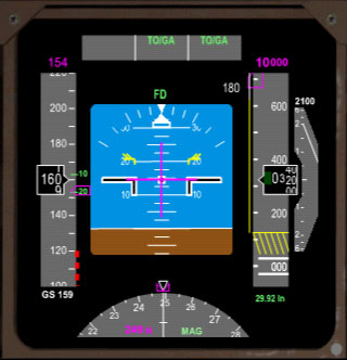
As soon as you're clear of the runway and your climb rate
is at least 500 feet per minute, set the landing gear to UP.
Climb and Cruise
Raise flaps on schedule. When the green number sign passes
on the speed tape of the PFD, you should raise flaps to that flap setting.
In the graphic above, I will be raising flaps to 10 when my speed increases
another few knots. Continue to do this until flaps are entirely up.
As soon as you're over 500 feet altitude,
select one of the A/P ENGAGE buttons on the autopilot
MCP.

This switches LNAV and VNAV from armed to active. The autopilot is now flying
the plane and you can sit back, complete this checklist, and monitor the
flight.
Move the landing gear lever to the OFF position. This
releases all hydraulic pressure from the gear and allows you to ensure that
it is securely locked in the up position.
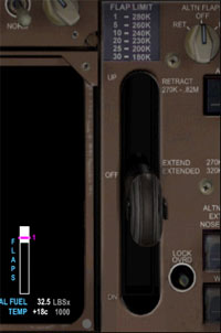
You'll notice that as the flight continues that the autopilot will control
altitude, speed, and direction.
Monitor the autopilot and speed as the aircraft levels off at 10,000 feet.
Turn off the TAXI and LANDING LIGHTS.
The SEATBELTS indicator may be turned off above 10,000 feet. If set
to AUTO, it will automatically turn off.
Set MCP ALT to 15,000 feet and hit the center of the ALT
dial to
command the autopilot to climb to our cruise altitude of 15,000 feet. The
normal cruise altitude of the 747 is much higher, but this is a very short
flight.
Set the TCAS BIASING mode to N. The TCAS system will now primarily
look for conflicts near your altitude.
Approach and Landing
As soon as you're established at 15,000 feet, open the COM panel.
Set AUTOBRAKES to 1. The runway at Edwards AFB is 15,000
feet long, so the lowest setting should work fine to stop us well before we
run out of runway.
Close the COM panel.
Open the FMC.
Click the INIT REF button. You will see the APPROACH REF
page. This page gives us two flap settings, with their corresponding speeds,
that can be used for approach. Flaps 25 is the standard approach flaps setting.
Click LSK 1R to copy the flaps 25 settings and VREF speed
to the scratchpad.
Click LSK 4R to set the approach flap and approach speed.
This will allows the autopilot and flight director to provide accurate flap
restriction speeds on approach. Take note of the approach speed value as
we will need it in a few moments.
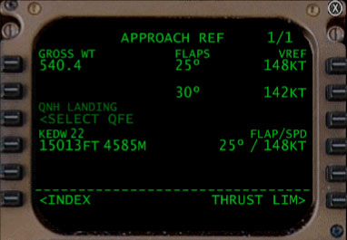
Click the NAV/RAD button. Note the heading as indicated next
to LSK 4L. This is the heading for the landing runway. It should be 224 degrees
for runway 22 at KEDW.
Close the FMC.
At about 10 miles from the VCV VOR, set MCP ALT to 0. Be
sure to do this well before you cross the T/D (Top of Descent) indicator
on the ND. Do not press the center of the ALT button or the autopilot will
descend to that altitude now. Simply dial the number into the ALT indicator.
This will allow the autopilot to begin it's descent at the scheduled time.
The autopilot will not descend below the altitude set in the MCP. Watch as
the plane begins the programmed descent near the VCV VOR.
Set the TCAS BIASING mode to BELOW. The TCAS
system will now primarily look for conflicts along your descent path.
Set the HDG to the runway heading (224 degrees). Do
not press the SEL button. Simply enter the HDG as a reference and as a set altitude
in case you abort the landing.
As soon as you begin the turn at the VCV VOR (base
leg) or your descent, set
the IAS/SPEED to approach speed + 5 knots. The approach speed is the
speed referenced in the FMC previously. In order to set the speed, you must
first click the center of the speed adjustment knob and then set the speed
to the correct setting. My approach reference speed was 148
knots, so I set the IAS/SPEED to 153. The plane will now begin to decellerate
to the indicated speed.

Use speedbrakes (/ key) to slow
you to your flaps 1 speed if your speed remains high (due to a steep
descent) or if your speed exceeds 250 knots below 10,000 feet. You want to be
close to your approach speed as you turn to final.
Lower flaps on schedule. Watch the speed tape
in the PFD. As soon as a flap setting indicator passes the current speed
marker, lower flaps to the next flap setting. For instance, when UP passes
the speed marker, lower flaps to 1. When 1 passes, lower flaps to 5, and
so forth until your flaps are at 25.
Lower the landing gear. The landing gear CAN
be extended when your speed is below 270 knots and SHOULD be lowered when
you set flaps 20. If you are approaching the turn to final and your speed
is well above approach speed and below 270 knots, lower the gear to increase
drag and help slow you down. Make sure you are at your approach speed with
flaps at 25 when you are several miles from the runway.
ARM the speedbrake (Shift + /). With the speedbrake
armed, it will deploy as soon as the main gears touch the runway.
Turn LANDING and TAXI lights ON.
As you complete the final turn, press the LOC and then
the APP buttons on the MCP.

LOC will instruct the autopilot to lock on to and follow the ILS localizer,
which will align your plane with the runway. APP will instruct the autopilot
to follow the glideslope and will enable the autopilot to complete a full
autolanding. The LOC and VNAV lights will extinguish when you press APP.
All three A/P lights should be on indicating that the autopilot is set up to
perform an autolanding.
Ensure that flaps are at 25, the gear is down, and that the plane
is properly following the ILS. Sit back and enjoy the autolanding. The
autopilot will fully control all aspects of the aircraft until touchdown.
If you'd rather land manually, you can disengage the autopilot by pulling
down on the DISENGAGE bar (or Z key), turning A/T ARM off, and setting F/D
to OFF. You will then have full control over throttle, pitch, and roll. Manually
keep your speed at approach speed + 5 knots and follow the ILS indicators
to the runway.
At around 50 feet, the autopilot will begin a flare and will gently (if everything
goes right) land about 500 feet from the runway threshold.
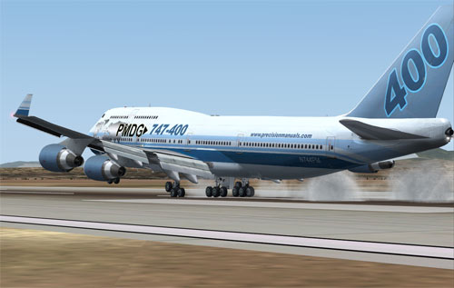
As the main wheels touch the ground, bring the throttles
to idle and then engage full thrust reversers (hold down F2 key). The
autopilot will perform a rollout maneuver that will keep the aircraft
centered on the runway. Braking is also performed automatically, though
engaging thrust reversers will decrease brake heating and wear. Do not
touch the controls except to engage thrust reversers - the plane will
do everything else.
At 80 knots, set throttle back to idle, disengaging thrust reversers.
As soon as, or shortly before, the aircraft comes to a complete
stop, DISENGAGE autopilot, set A/T ARM to OFF, and turn
the F/D OFF. The
aircraft is now in your control and you may begin your taxi. When you apply
taxi thrust, the speedbrakes will retract. Exit the runway when able and
taxi toward the gate or parking area of your choice. The airport here is
HUGE, so you've got plenty of time to work through the remainder of the checklists.
Taxi In, Parking, and Shutdown
Set flaps to 0.
Set AUTOBRAKES to OFF.
Set the TCAS to STBY.
Set LANDING and STROBE lights to OFF.
START the APU. This will allow us to turn off
the engines, but still power the aircraft until ground power is available.
Set the parking brake as soon as you're fully
stopped at the gate or parking area of your choice.
Turn ON APU GEN 1 and APU GEN 2.
Set ENGINE BLEED valves to OFF on the pneumatics panel.
Ensure that APU BLEED is ON. This ensures that air flow continues while the
passengers deplane.
Set ENGINE hydraulic pumps OFF.
Set FUEL control switches to CUTOFF on the THR panel. This
will turnoff the engines.
Turn OFF the seatbelt indicator on the COM
panel. This indicates
that the passengers may now deplane.
Open a door or two (or 15). Or let the flight attendants do it.
Turn OFF the BEACON lights to indicate that the
plane is properly parked and will not be moving. This alerts ground crew
that they are free to connect ground power and unload baggage, etc.
Ground power should now be available. However, ground
power is not available at all airports. You would
typically switch to ground power and turn off the APU at this time, but if
ground power is not available, leave the APU on to power the aircraft until
you're done with the shutdown checklist.
Turn OFF YAW DAMPERS.
Turn OFF hydraulic DEMAND switches.
Turn OFF CONT ignition.
Turn OFF AUTOSTART.
Turn OFF all three IRS systems.
Turn OFF L and R UTILITY.
Turn OFF all fuel pumps. Tank 2 aft will remain on until the APU is
shutdown.
Open all XFEEDs. This allows fuel to flow freely if the aircraft is refueled
on the ground.
Turn OFF WINDOW HEAT.
Turn OFF AFT CARGO HT (if on).
Turn OFF TRIM AIR.
Turn OFF GASPER.
Turn OFF
UPR and LWR RECIRC fans.
Set all three PACKS to OFF.
Turn OFF APU BLEED.
Turn OFF APU GEN 1 and GEN 2 (if on)
Turn OFF the APU (if running)
Turn OFF EXT
PWR 1 and 2 (if available)
Set all internal and external lighting to OFF.
Set the STBY POWER selector to OFF.
Turn off the BATTERY.
The aircraft is now in the same cold and dark condition that it
was in when we boarded. Congratulations on completing the flight!


